Development design / CAE analysis / 3D modeling
This is an attractive job to create the future of mobility through the development and improvement of new vehicles. We offer the best services to play an important role in achieving sustainable mobility development.
Development design
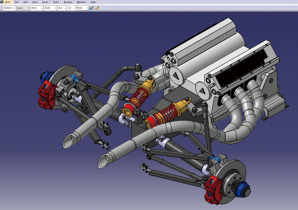
By skillfully operating high-end three dimensional CAD “CATIA”, we design automobile parts that are delivered to users all over the world.
Work content
In design, we coordinate with related departments to determine the final product shape so that it meets the requirements necessary to realize the product.
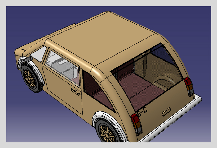
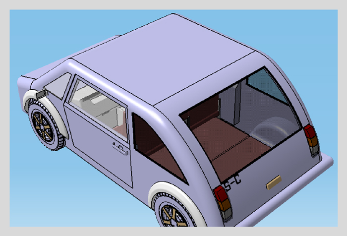
To determine the shape, we use CATIA to model a shape that incorporates our own technology and ideas in a 3D space, and based on this, we repeat various studies with related departments.
We measure performance from various perspectives, such as compliance with the laws and regulations of each country, environmental performance and collision safety performance, and work as a team to derive a shape that meets all performance requirements.
Based on the wealth of knowledge, experience, and know-how we have accumulated over the years, specialists with high-level modeling skills are dispatched as designers, or entrusted or contracted for design work.
Work flow
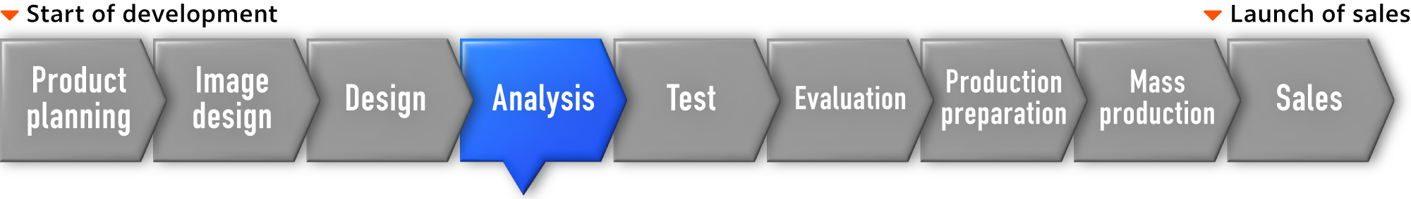
Flow of automobile development
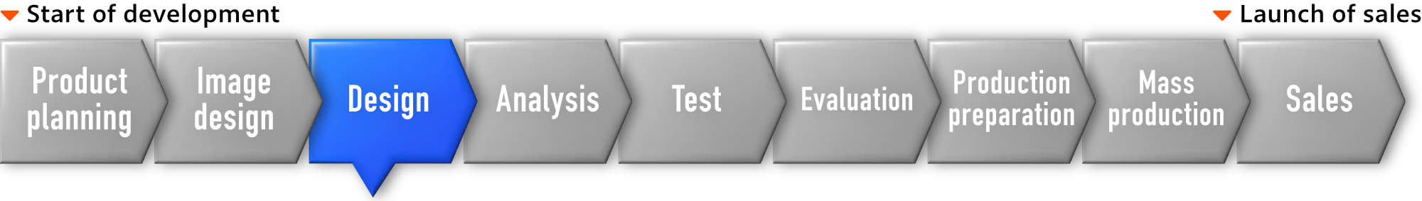
Design work flow
-
- Design concept
- Determine the concept and base design.
-
- Basic cross section
- Create a cross section to check whether the space where each part exists is established.
-
- Layout
Simple 3D data creation - Create simple 3D data based on the basic cross section.
- Layout
-
- Coordination with related departments
- Coordinate with related departments and verify any problems based on the simple 3D data.
-
- 3D data creation
- Create detailed 3D data for one vehicle.
When a problem occurs基本断面に戻る
-
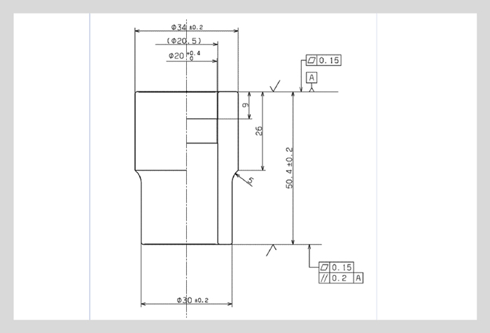
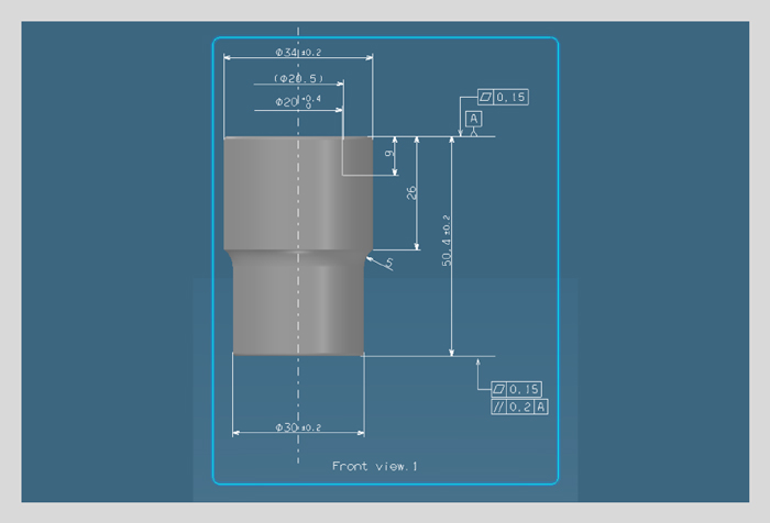
- Drawing creation
- Create a drawing for each part.
-
- Drawing issue
- Issue a drawing formally.
Tools used
- CATIA V5/V6CATIA (Computer-graphics Aided Three-dimensional Interactive Application)
3D CAD developed by Dassault Systems of France
It is a high-end 3D-CAD widely used in the automobile and aviation industries, and is a tool that can efficiently perform the product development process and improve the design quality.
A wealth of commands suitable for 3D modeling are implemented to create objects (3D) in virtual space in an intuitive way.
In addition, in recent years, physical behavior is often simulated on a computer, and a function to evaluate it is also provided.
With these tools, it is possible to perform placement layout, verification (analysis), and drawing creation from part design, and it is an essential tool for automobile development.
Work results
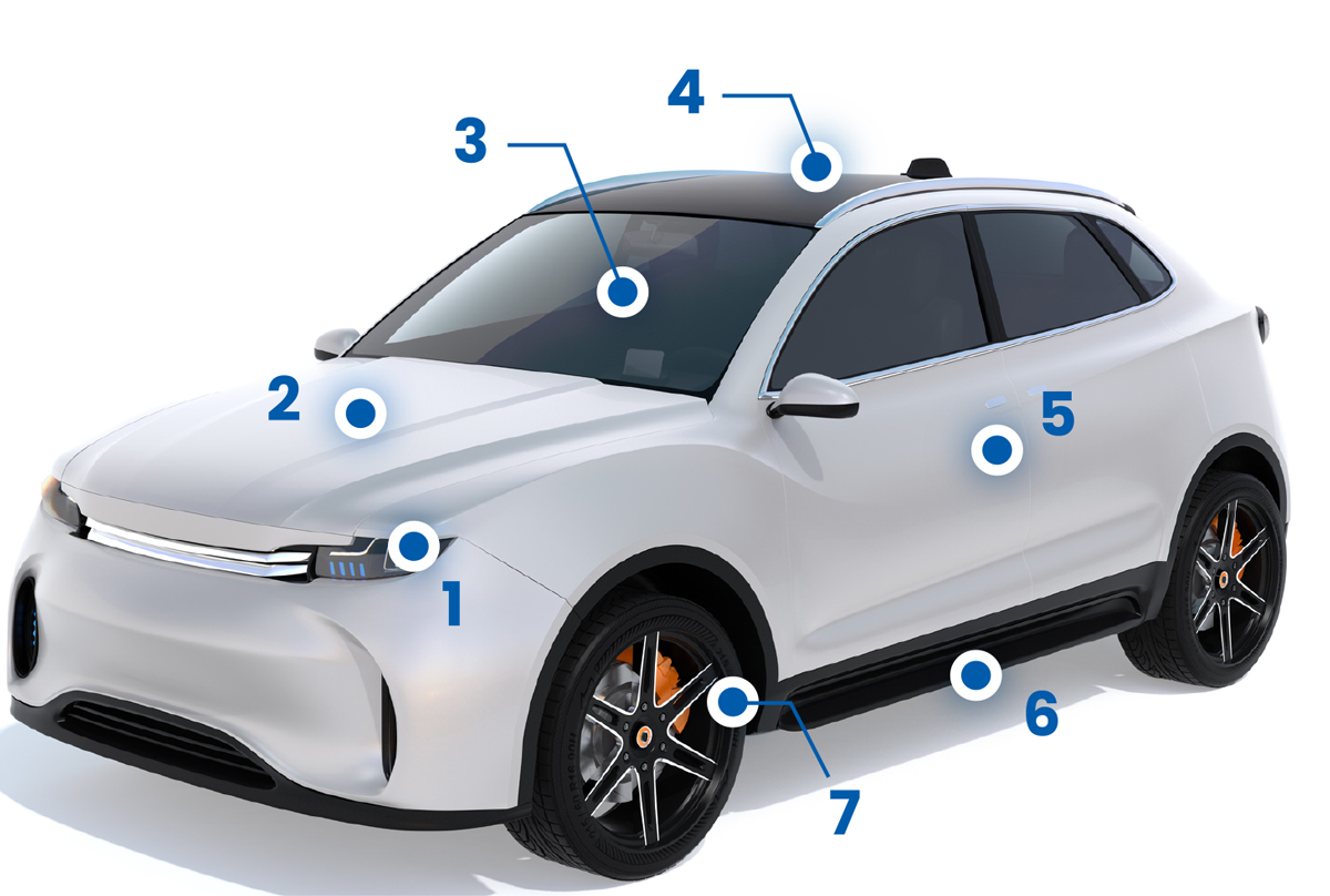

1 Lights and electrical systems
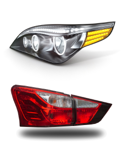
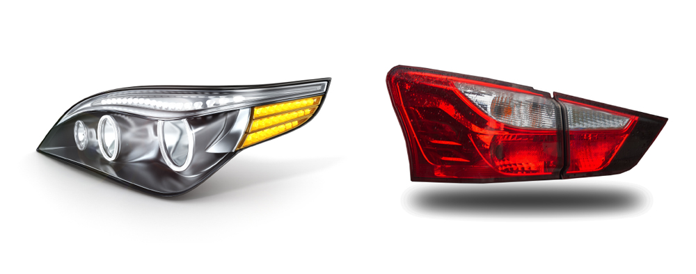
- Headlight
- Rear combination light
- Turn signal light
- Bumper
- Horn
- Meter
- Various types of sensors
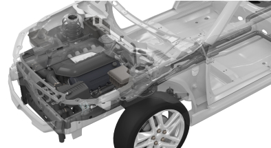
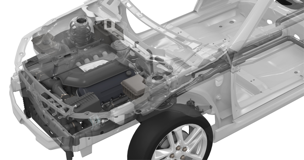
2 Engine system
- Cylinder head / block
- Piston
- Crankshaft
- IPU (battery for HEV)
- Cooling system
- Alternator
- Oil pump
- Water pump
- Harness, etc.
3 Interior and safety equipment
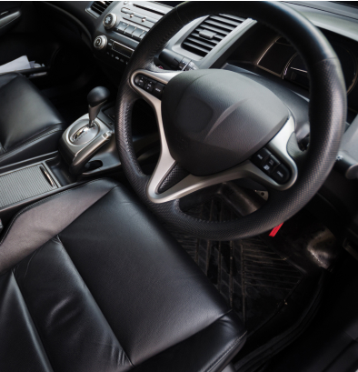
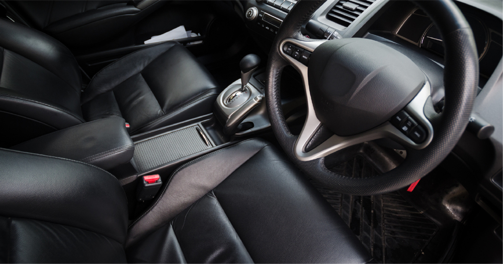
- Instrument panel
- Console
- Glove compartment
- Roof lining
- Door lining
- Floor / Cargo Lining
- Front / Rear seat
- Seat belt
- Airbag, etc.
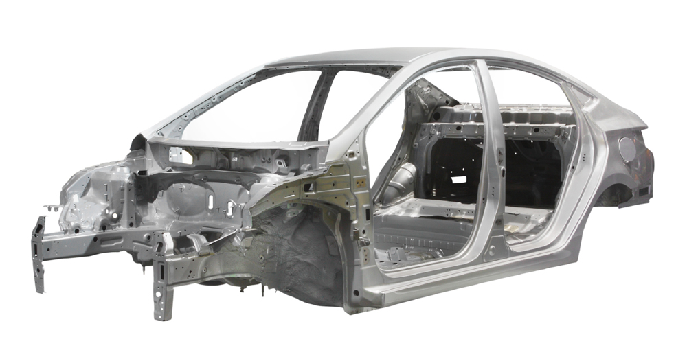
4 Upper body
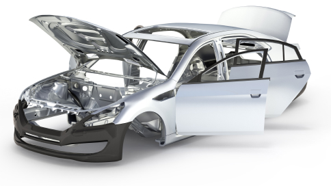
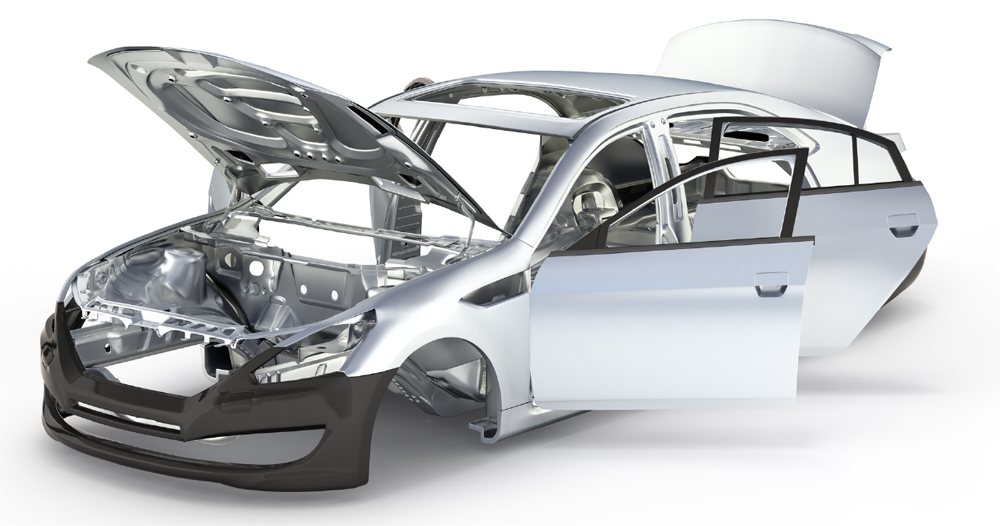
- Roof panel
- Hood
- Inside / Outside Panel
- Fender panel
- Cowl top, etc.
5 Exterior
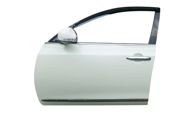
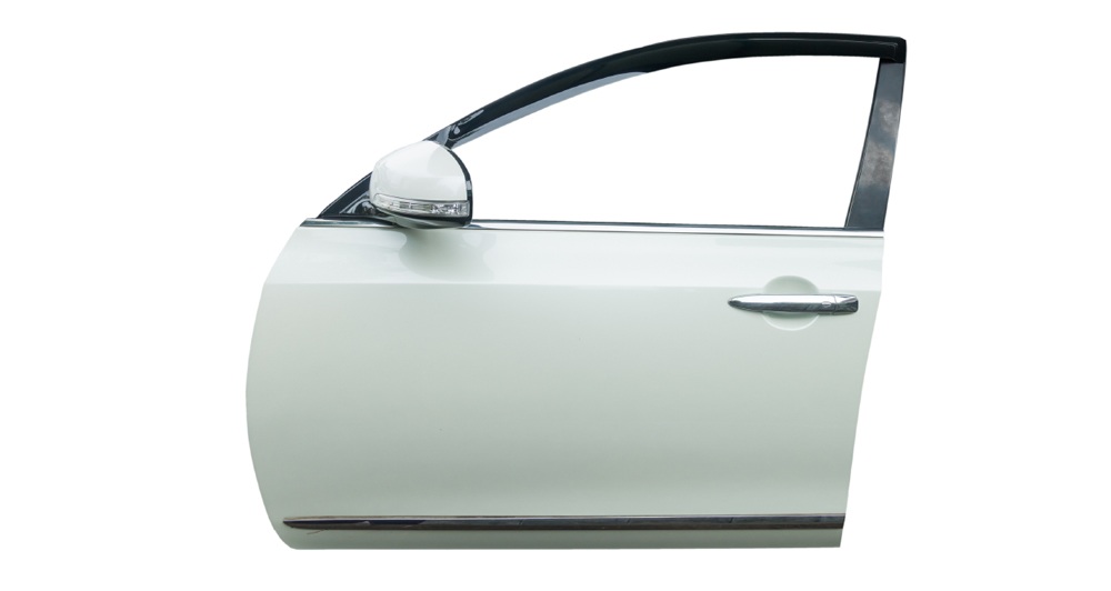
- Door panel
- Door glass
- Inner / Outer handle
- Sash
- Seals, etc.
6 Under body
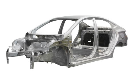
- Front / Rear floor
- Side frame
- Center tunnel
- Wheel house
- Bulkhead
- Under cover
- Fender cover, etc.
7 Powertrain / Chassis
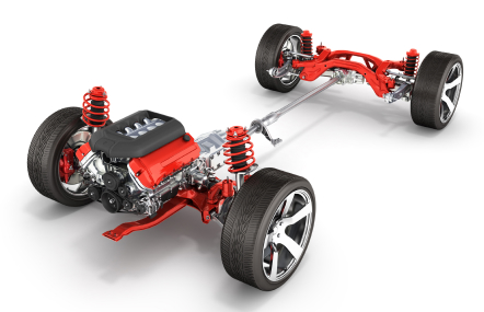
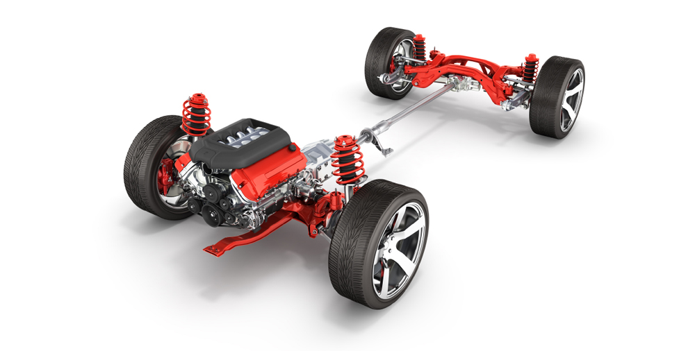
- Clutch
- Transmission
- Drive shaft
- Wheel / Tire
- Axle / Brake
- Steering
- Fuel tank, etc.
CAE analysis
It is the work to predict and evaluate the performance and behavior of products by computer simulation.
Work content
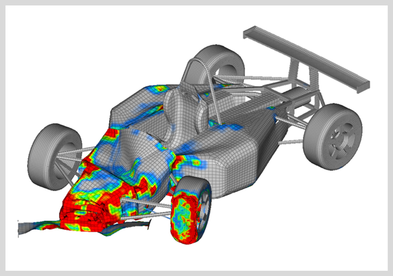
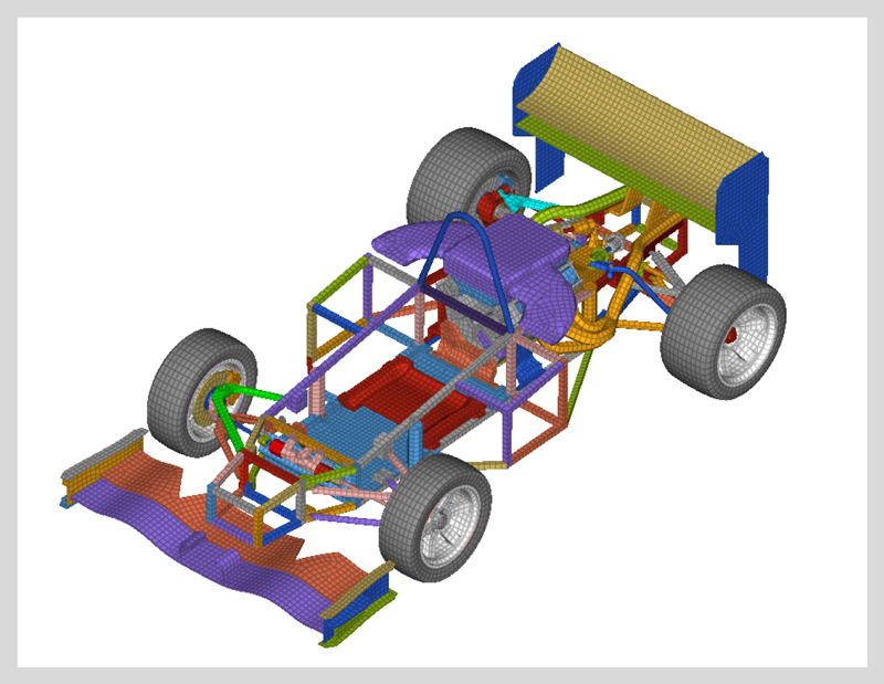
Automobile collision CAE analysis is to predict and evaluate the behavior and safety of automobiles when they encounter accidents or collisions using computers.
This makes it possible to evaluate the safety of the vehicle while minimizing actual collision tests.
In such analysis, the design, structure, material properties, collision speed, and angle of the automobile are first incorporated into a computer model.
Next, based on these information, the computer performs mathematical numerical calculations and simulates data on various factors at the time of collision.
We mainly support the evaluation of the following points as a collision CAE analysis.
- Model creation
Create a 3D model of the target car or structure on a computer. This model precisely represents the shape, structure, and material properties of the target object. - Structural analysis
Evaluate how effectively the strength and deformation of the vehicle’s structure and the design of the deforming space absorb impacts.
Occupant behavior analysis: Assess occupant safety by predicting how they will move and how much force will be applied in a collision.
Based on the results of these analyses, automobile manufacturers can optimize designs and improve safety functions to increase safety before conducting actual collision tests.
It also serves to streamline product development procedures, and save costs and time.
In addition, we have the following analysis work results.
- – POWER UNIT-related
- – Light assembly / Interior-related
Work flow
Flow of automobile development
Analysis work flow
-
- Target setting
Planning concept - Set a target to satisfy each requirement, and define the characteristic values to satisfy the target values.
- Target setting
-
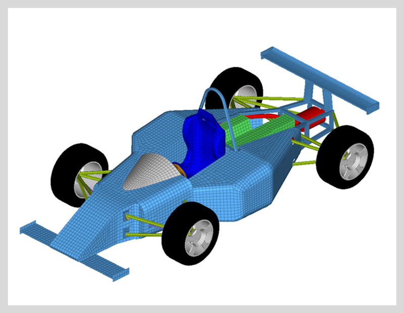
- Mesh generation
Consideration of shape - Create a 3D model of the target car or structure on a computer. This model precisely represents the shape, structure, and material properties of the target object.
- Mesh generation
-
- Boundary condition setting
Model building - Set the boundary conditions on the model. This includes collision velocity, direction, angle, and other initial conditions.
- Boundary condition setting
-
- Execution of analysis
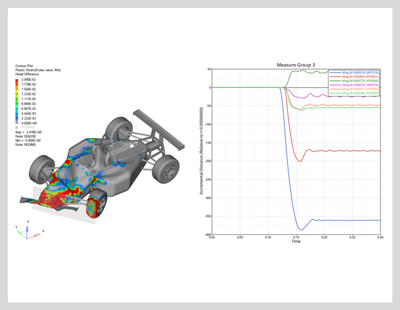
- Based on the set conditions, the supercomputer executes the analysis and writes out the results of the predicted behavior of the object at each hour.
-
- Evaluation of results
- Evaluate the results of the simulation and analyze the deformation, stress distribution, displacement, etc. of the structure. This allows to evaluate and improve the performance.
-
- Coordination with other departments
Report of judgment results - Report the evaluation results and coordinate with other departments for prototype and mass production.
When a problem occursメッシュ生成形状検討に戻る
- Coordination with other departments
Tools used
- ANSA(Developed by BETA CAE Systems)
- Hyper Works(Developed by ALTAIR)
Computer-Aided Engineering (CAE) software for analysis is a tool that utilizes computers to analyze the collision and collision-related behavior of structures.
These tools are useful for simulating the effects of physical collisions and forces in virtual space, for identifying problems during the development stage, and for optimal design.
Based on a CAD (Computer-Aided Design) model, input the shape of an object, material characteristics, boundary conditions, etc., and simulate actual behavior on a computer.
CAE software is used in a variety of industrial fields, including the automotive and aerospace industries, and contributes to improving the efficiency and quality of product design and development processes.
| Other achievements | Software used |
|---|---|
| Computational fluid dynamics | FLUENT/Flowmaster/Particle_works |
| One-dimensional analysis | SimulationX/GT-SUITE/GT-POWER |
| Shape optimization | mode FRONTIER |
| Multibody dynamics analysis | EXCITE/RECURDYN |
| Vibration analysis | PS-X |
| Optical analysis | SPEOS |
3D modeling
We support manufacturing in various areas by 3D modeling using high-end 3D CAD “CATIA”.
Work content
3D data is used in various fields in the automotive development field.
We are engaged in 3D modeling of automotive parts and production line equipment, as well as data construction to utilize 3D data drawn by designers for various types of verification.
Tools used
- CATIA V5/V6CATIA(Computer-graphics Aided Three-dimensional Interactive Application)
3D-CAD developed by Dassault Systems of France
It is a high-end 3D-CAD widely used in the automobile and aviation industries, and is a tool that can efficiently perform the product development process and improve the design quality.
A wealth of commands suitable for 3D modeling are implemented to create objects (3D) in virtual space in an intuitive way.
In addition, in recent years, physical behavior is often simulated on a computer, and a function to evaluate it is also provided.
With these tools, it is possible to perform placement layout, verification (analysis), and drawing creation from part design, and it is an essential tool for automobile development.
Work results
Modeling of production equipment data (2D drawing → Modeling → Assembly → Movable setting)
Automotive data conversion (CATIA V5 → V6) / 3D drawing registration
Parts composition disassembly / Part application input / Part attributes input (material, weight, thickness, etc.) / Data check before drawing issue
3D welding element creation / Modeling of door parts bending
-
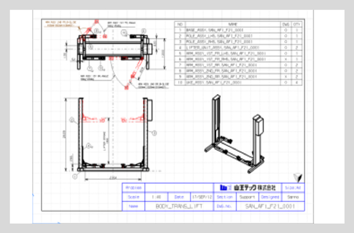
2D drawing -
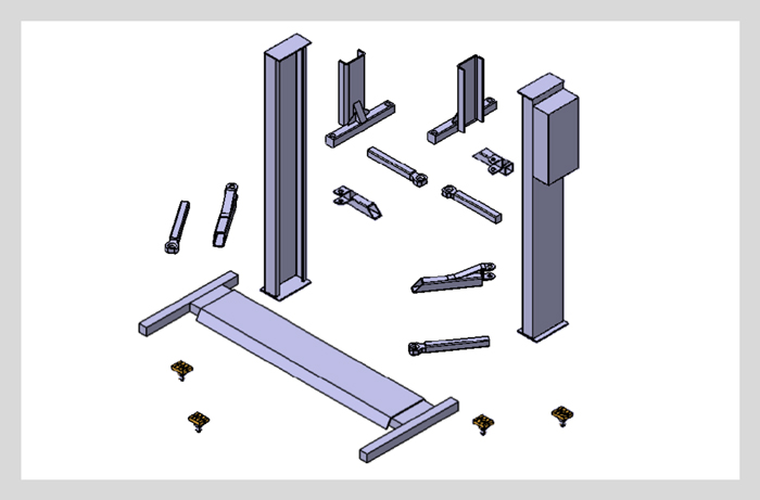
Modeling -
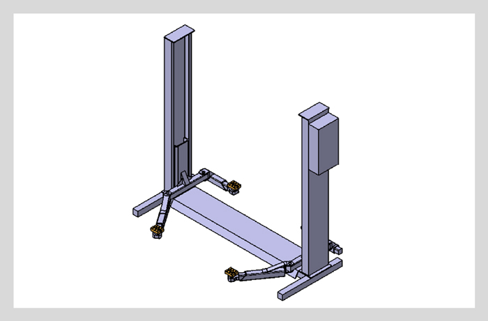
Assembly -
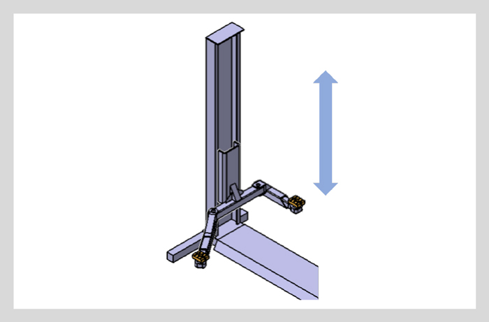
Movable setting